UT-Trainer — Ultrasonic Testing Simulator

Full version & prices →
● Trial version — limited functionality

Real device photo with interactive controls — the same UFD 900 used in my Udemy courses UT Level 1 and UT Level 2.
In this trial version you calibrate (adjust) the probe on a step block, then find flaws in a steel plate and identify an unknown material by ultrasound. Use the Tour function to be guided step by step.
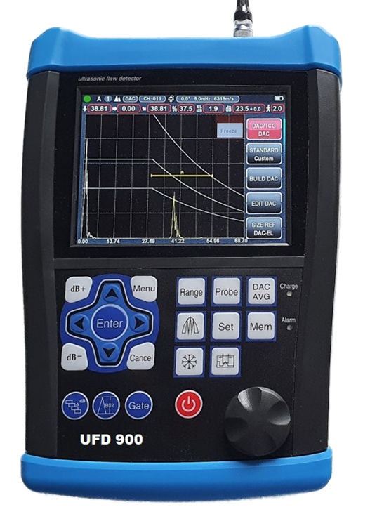
UFD 900 ultrasonic flaw detector
◍ POWER OFF
COUPLE
DAC
ALARM

Reference

40 mm Steel — 5920 m/s Steel — 5920 m/s

Position: 150 mm

Single-element straight-beam probe.

Drag the probe along the plate's surface. Click it to lift it off (line goes flat) or place it back down (coupled).

Live readout

SelectedRANGE
Gain12.0 dB
Range100 mm
Velocity (MATVEL)5920 m/s
Gate30–50 mm @40%
Gate reading– –
DAC/AVG points0

How to use

Press Power first. The 5 tiles on the right of the display are real menus, exactly like the original device: Range, Probe, Gate, Set and Mem jump straight into their own menu (BASE/PROBE/GATE/SET/MEM), DAC/AVG cycles DAC → AVG → off. The Menu key (between dB+ and ↑) opens the grid of function groups — move the cursor with the D-pad, Enter loads a group, Cancel closes it without changing anything. Inside a menu, tapping a tile selects it (pink outline) or fires the action, and ↑/↓ step through a menu's own functions, scrolling if it has more than 5. Change a value with the rotary encoder (click left/right or scroll wheel) or the ◀/▶ arrows. dB+/dB− change gain directly, even outside the GAIN menu. The round key with the zigzag icon is AutoGain. The second square icon is Zoom. Freeze shows "Freeze" on screen. On the test specimen to the right, drag the probe along the plate's surface or click it to lift it off / place it back down — without coupling the trace stays flat. A hidden flaw sits somewhere along the plate: scan slowly and watch for an extra echo ahead of the first backwall signal — like a real near-surface reflector, it rings its own repeat-echo train too (fading faster than the backwall's), so don't mistake those for deeper flaws.

Material calibration (Probe)

Picking a material here dials MATVEL to its reference velocity, same as typing it in on the real device. Every test specimen is steel (5920 m/s) except the DAC Block (aluminium, 6360 m/s — no mystery, it’s labeled on the block) and the Unknown Material block, whose real velocity is deliberately hidden — its known 30 mm thickness only reads correctly once MATVEL is right. Wrong MATVEL = wrong depth reading everywhere, just like on the real device.

Angle beam probe — refraction angle

Pick the angle stamped on your probe (ANGLE in the PROBE menu). The V2-Normal block carries a scale for checking that angle against the Ø5 hole; it runs from 35° to 65°, numbered at 40/50/60/65 like the real block — so a 70° or 75° probe has no mark to index against there.

Crystal size (rectangular element)

The element's real width×height, stamped on the probe housing — a bigger crystal narrows the beam's divergence and raises its near-field length.

Nominal frequency

Also stamped on the probe housing (X_FREQ in the PROBE menu — same setting, just picked here too since it's part of the same probe ID).

SET files

Please confirm

Not available

Enter name

Report

Test Result

Parameters

Date & Time

Read-only in this UT-Trainer — the instrument's clock always follows this device's own system clock.

DEV — couplant line geometry

Live-adjusts the yellow couplant line. Nothing here is visible to a normal viewer — sliders only, no numbers move anything until you drag one.

Applies to

Sliders below load from — and on OK, write into — every checked probe. Each one starts with its own default; check more than one to make them share a value.

Live-trace jitter ("Zappeln")

Sound attenuation — typical values

Typical attenuation of the longitudinal wave in dB/m at three probe frequencies — the values the UT-Trainer uses for its specimens (source: K. Ono, “A Comprehensive Report on Ultrasonic Attenuation of Engineering Materials”, Applied Sciences 10 (2020) 2230; aluminium matched to a real 30 mm block). Attenuation rises with frequency and grain size; for transverse waves (angle probe) the trainer uses twice the value. Real materials differ widely with structure and heat treatment, so for accurate work the attenuation is measured on the test piece itself. For the AVG evaluation enter the value under “Sound attenuation” (CORRECT box or EDIT AVG tile).

Sound velocities — common materials

Typical longitudinal- and transverse-wave velocities. Where the usual reference tables (Olympus/Evident, NDT Resource Center, Onda, Waygate Krautkrämer, Dakota) differ by more than about 2 %, the range is given — mostly because of alloy, heat treatment or, for cast iron, the graphite form. Liquids carry no transverse waves. For accurate measurements set VELOCITY on a reference block of the same material with known thickness, as with the Unknown Material specimen.